

How custom CNC cutting works
Posted on in the basicsHere at Neal's CNC, we often get inquiries where the customer says something on the order of "I don't know how this works, this is my first time". Let's go through the CNC process so you know a bit better what to expect. I'm discussing CNC routing in this post, but the process is very similar for laser, waterjet, plasma cutting, and most other CNC machinery.
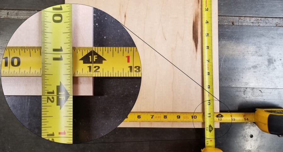
CNC means Computer Numeric Control. And THAT means exactly what it sounds like: your parts are going to be cut according to extremely precise numbers, controlled by the computer. If you need a 12" square part, you will get a part that is exactly 12" square, not 11-7/8" by 12-1/64". But if you do need one that is 11-7/8"x12-1/64", you will get exactly that.
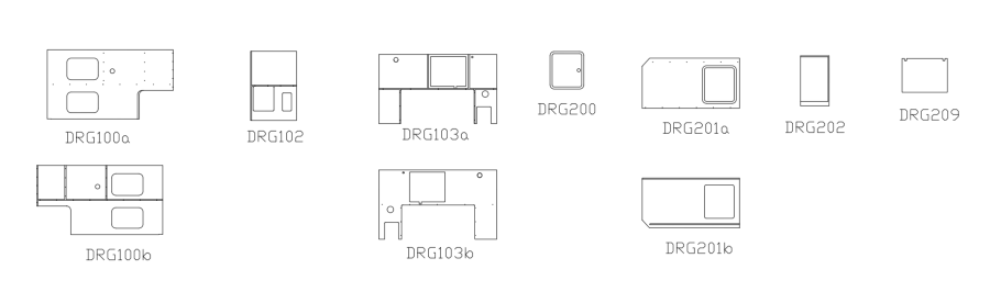
In order to make these precise parts, the CNC operator needs to know precisely where the part's edges are. The most common way to get this information is from a technical drawing. The drawing must be in electronic or CAD format, which stands for Computer Aided Design. There are many varieties of CAD formats, and each CNC machine may have slightly different format requirements. Neal's CNC is able to accept a wide range of these which we can convert as needed. For 3d work, we can use STEP, 3dm, IGES, and some STL file types. For 2d work, we simply require a vector drawing of the pieces to be cut, such as a DXF or Adobe Illustrator file. A raster file, such as a photograph or bitmap, doesn't store the information in a CNC readable way. Paper drawings (or photos of paper drawings) need to be redrawn in a CAD program such as AutoCAD, Solidworks, Illustrator, or many others, either by the customer or by Neal's CNC.
With a drawing of the part(s), we turn to our CAM software, which stands for Computer Aided Machining. This is the process of interpreting the drawing into the precision numeric moves that the machine will make during cutting. This is the time when the programmer tells the software what bit size to use, how deep to make the cut, how fast to spin the spindle with the cutting bit in it, how fast to move the cut through the material, and a few other parameters depending on the type of cut. The CAM software takes that information and applies it to the drawing shapes, yielding "g-code", which the CNC router controller can read.
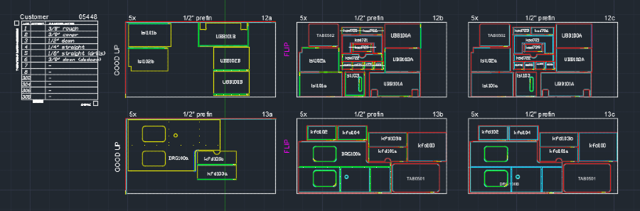
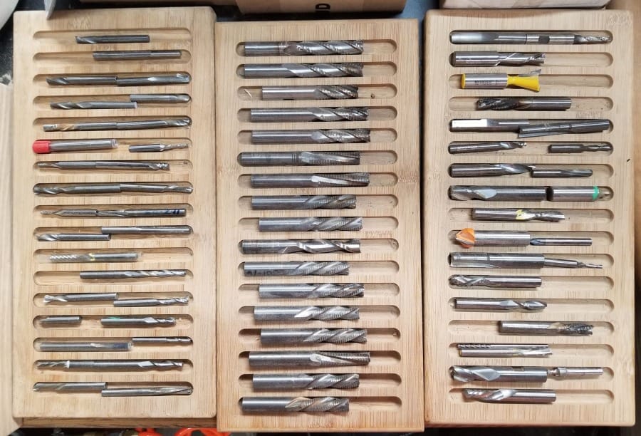
The g-code file, along with a cut sheet showing the layout of the shapes to be cut and the bit profile used in the cut, is passed to the machine operator. The operator decides which of the thousands of specific bits available will suit this cut best, within the parameters coded up in the CAM step. For example, the cut sheet may specify that a 1/4" diameter bit is used. The operator must choose a 1/4" bit from a variety of parameters such as upcut, downcut, compression, single flute, double flute, triple flute, fishtail, coated or uncoated, and many more. They load the chosen bits into tool holders, program the CNC controller with those bits' details, place the correct material onto the machine bed, and run the cut. A simple cut may take only a minute or two; a complex cut can take an hour or more and require multiple gcode files and precise movement of the stock during pauses in the cut. When the cut is done, the operator removes the finished parts, clears the table bed of sawdust, and starts again on the next cut.
One customer job may take only one sheet and be finished cutting in an hour. Or, it may take hundreds of sheets and run for weeks. At Neal's CNC, most of our jobs are somewhere in between.